An In-Depth Analysis of Phenolic Resin

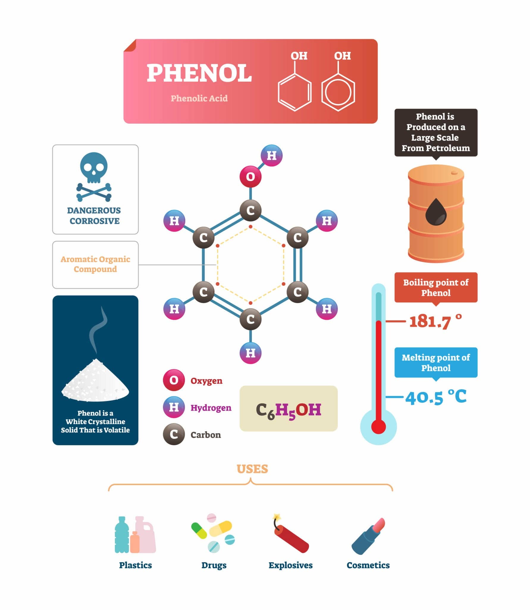
When discussing the pillars of thermosetting resins, Phenolic Resin stands out as a true pioneer. As one of the top three thermosetting materials, PF combines historical depth with unyielding modern relevance. From the standard laboratory synthesis of phenol and formaldehyde to advanced modifications for aerospace and green construction, phenolic resin continues to dominate severe-service industrial applications.


1. The History of Phenolic Resin Development

The commercialization of Phenolic formaldehyde resin (PF) was not a straight line, but rather a masterclass in solving material brittleness and processing bottlenecks:

  • 1872 – 1903 (The Exploration Era): German chemist A. Baeyer first observed the reaction between phenols and aldehydes. Early attempts by investigators like W. Kleeberg and L. Blumer yielded "Laccain" (a shellac substitute used as a varnish resin), but these early polymers were plagued by severe shrinkage, cracking, and a porous structure caused by water evaporation during uncontrolled curing.
  • 1907 – 1910 (The Bakelite Breakthrough): The legendary L. H. Baekeland revolutionized the industry by introducing his patented "Heat and Pressure" curing process, founding the Bakelite Company in 1910. Baekeland cracked the code: the polymer’s thermoplastic or thermosetting nature depends strictly on the phenol-to-formaldehyde molar ratio and catalyst type. By introducing wood flour (wood dust) and other functional fillers, he successfully eliminated the resin's inherent brittleness.
  • 1911 – 1930s (Formulation Expansion): Aylesworth discovered that adding Hexamethylenetetramine (Aminoform / Urotropine) could crosslink thermoplastic Novolac resins into insoluble, infusible networks, unlocking excellent electrical insulation properties. Simultaneously, K. Albert incorporated Rosin to produce oil-soluble phenolic resins. When blended with tung oil, it achieved rapid-drying, highly weather-resistant coatings, opening new frontiers in the paint and varnish industries.


2. Synthesis & Chemistry: Novolac vs. Resol
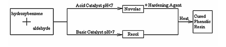
 

The polycondensation of phenolic resins follows two distinct chemical pathways based on pH and monomer balance:

Resin Type Catalyst Type Molar Ratio (Phenol : Formaldehyde) Curing Mechanism Key Structural Features
Resol (resol phenolic resin) Alkaline Formaldehyde is in excess Heat-activated self-crosslinking. Contains abundant active methylol groups (-CH2OH); linked via methylene and ether bonds.
Novolac (Thermoplastic) Acidic Phenol is in excess Requires a curing agent to crosslink. Cured via methylene linkages; nearly free of residual methylol groups; highly shelf-stable.


3. Current Status and Development of Phenolic Resins

Globally, the market demand has shifted from standard commodities to high-performance, modified grades. Historically, China exported low-end commodity-grade phenolics while importing high-value, electronic-grade variants. Bridge-building innovations are fast closing this gap.

To meet tight quality control criteria and eliminate batch-to-batch variance, the manufacturing topology is evolving rapidly:

  • Reactor Scaling: Upgrading from legacy 5m3 vessels to fully automated, computerized 30m3 reactors.
  • Advanced Cooling: Utilizing steel-belt flaking with thin-layer cooling technologies to stabilize resin properties during discharge.
  • Continuous & Suspension Polymerization: Transitioning toward continuous tubular reactor systems and advanced suspension processes to yield spherical, free-flowing granular phenolic resins with superior processability.


Website: www.elephchem.com

whatsapp: (+)86 13851435272

E-mail: admin@elephchem.com
Top

Suspension-grade phenolic resin

Traditional phenolic resin produced via bulk polymerization often suffer from broad particle size distribution, high dust emission, and batch-to-batch instability. To overcome these limitations, advanced suspension polymerization has emerged as a premier methodology for manufacturing narrow-distribution, eco-friendly, and highly stable spherical phenolic micro-resins.


Section 1: Synthetic Mechanism and Process Optimization

[Raw Materials: Phenol + Formaldehyde]

⇓ (Oxalic Acid / Acid Catalyst)

[Linear Novolac Oligomers]

⇓ (Water Phase + Polyvinyl Alcohol (PVA) Dispersant)

[Stable Spherical Suspension Droplets]

⇓ (Hexamethylenetetramine (HMTA) / Crosslinking Agent)

[Cured Spherical Phenolic Microbeads]

The synthesis utilizes an acid-catalyzed system (such as oxalic acid) to promote the initial condensation of phenol and formaldehyde. A critical phase of this process is the inversion into a water-borne suspension. Polyvinyl Alcohol (PVA) is introduced as a highly efficient polymeric dispersant to precisely control the interfacial tension and prevent droplet coalescence.

Subsequently, Hexamethylenetetramine (HMTA, or Urotropine) is introduced as both a curing agent and a methylene donor. This crosslinking reaction incorporates unique benzoxazine ring structures into the resin skeleton, which are inherently absent in conventional bulk-polymerized counterparts.


Section 2: Morphological Characterization via SEM

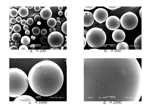
Scanning Electron Microscopy (SEM) and statistical software analysis demonstrate that the suspension-derived phenolic resins exhibit an excellent spherical morphology. Depending on the Formaldehyde-to-Phenol (F/P) molar ratio, the average volumetric grain diameter can be tailored between 102µm and 120µm.

Key Technical Parameters of Commercial Grades:

  • Appearance: White to light-yellow microspherical powder
  • Melting Point: 80–125°C (Customizable)
  • Gel Time (at 150°C): 10–100 s
  • Free Phenol Content: < 5%

This highly uniform spherical geometry eliminates the need for mechanical crushing, thereby preventing agglomeration, enhancing storage stability, and significantly optimizing downstream processing performance in compression and injection molding.


Section 3: FT-IR Spectroscopic Analysis

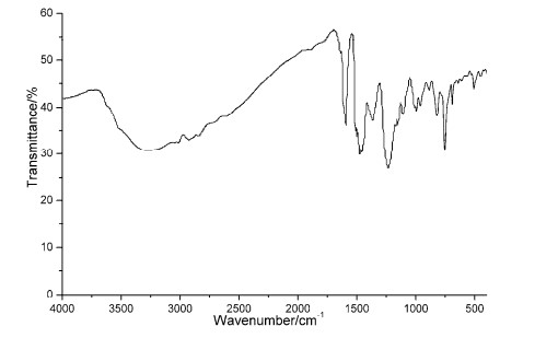
FT-IR analysis confirmed the exact molecular configuration of the suspension phenolic matrix. The broad and intense absorption band spanning 2500 - 3700cm-1 corresponds to the polymeric -O-H stretching vibrations and C-H groups. Characteristic aromatic vibrations include:

  • C=C Aromatic Ring Stretching: Observed distinct peaks at 1450--1600cm-1.
  • Asymmetric Ether Linkage (ArCOCAr): Identified via a sharp peak at 1240cm-1.
  • Regio-substitution Vibrations: Out-of-plane bending vibrations at 822cm-1 (indicative of 1,4- and 1,2,4-substituted benzene rings) and 756cm-1 (indicative of 1,3- and 1,2,3-substituted domains) verify successful multidirectional network propagation.


Section 4: Thermogravimetric (TG) Kinetic Profiles

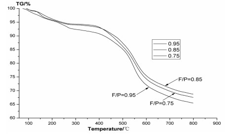
Thermogravimetric Analysis (TGA) highlights the superior thermal degradation resistance of the suspension-processed matrix over conventional solution-processed resins. The pyrolytic kinetics proceed across three distinct thermo-physical steps:

  • Ambient to 279.3°C (Desorption Phase): Minor mass loss (5.89-7.32%) occurs, ascribed to the volatilization of entrapped trace free monomers and moisture derived from post-condensation reactions.
  • 279.3°C to 401.8°C (Thermal Plate): The matrix achieves an elite state of thermal equilibrium with minimal weight alteration (as low as 0.27% loss at F/P=0.75), validating its exceptional high-temperature integrity.
  • 401.8°C to 638.7°C (Primary Pyrolysis): Major thermolysis occurs due to network fragmentation, liberating H2O, low-molecular phenols, CO2, and light hydrocarbons (CH4).
  • Char Yield Optimization: At 800°C under an inert nitrogen ambient, the residual char yields reach up to 68.71% (optimized at F/P = 0.85). This high carbon retentivity underlines its performance in refractory and high-friction applications.


Section 5: Non-Isothermal Curing Kinetics via DSC

Differential Scanning Calorimetry (DSC) curves at multiple heating rates (5, 10, 15, 20℃/min) reveal that the crosslinking mechanism is strictly exothermic. For temperatures under 170°C, the reaction kinetics are governed by the condensation of hydroxymethyl moieties on the phenolic core to generate methylene (-CH2-) and ether bonds (-CH2OCH2-). Above 170°C, benzyl ether decomposition and rearrangement dominate.

The absence of sharp, discrete endothermic spikes indicates that endothermic volatilization and exothermic crosslinking overlap continuously, yielding a smooth curing curve. This attributes to a well-controlled, gradual curing process crucial for defect-free polymer matrix composites.


Suspension-polymerized Phenolic formaldehyde resin represents a significant technological leap over traditional bulk resins. By deploying optimized F/P ratios and high-performance stabilization systems like PVA, manufacturers can achieve precise control over particle morphology, narrow molecular weight distribution, and outstanding thermal stability. This high-purity, spherical phenolic resin stands as an ideal solution for upgrading demanding industrial polymer matrices.


Website: www.elephchem.com

whatsapp: (+)86 13851435272

E-mail: admin@elephchem.com
Top

FFU Core Equipment for Modern Cleanrooms

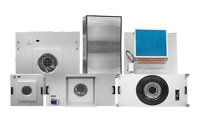
FFUs are self-powered units that operate independently of the central air conditioning system's supply pressure, handling the entire process of air intake, filtration, and clean air delivery. Their operating principle is as follows: the fan draws air in from the top of the unit; the air passes through two stages of filtration—pre-filtration and high-efficiency filtration—before being discharged across the entire outlet surface at a uniform velocity (typically 0.45 m/s ± 20%). This design ensures a very high level of air cleanliness and establishes a stable, unidirectional laminar airflow at the outlet, effectively preventing secondary contamination caused by air mixing.


 Core Components and Operating Principles 

FFUs typically consist of the following key components:

Housing: Acts as the structural framework; usually made of materials such as Al-Zn coated steel, stainless steel, or powder-coated cold-rolled steel, offering a combination of lightweight durability and corrosion resistance.

Fan: The core power component; typically a direct-drive centrifugal fan featuring a long service life (over 50,000 hours), low noise, maintenance-free operation, and stepless speed control.

Filter System: The core purification component; includes High-Efficiency Particulate Air (HEPA) filters (≥99.97% efficiency for 0.3μm particles) or Ultra-Low Particulate Air (ULPA) filters (≥99.9995% efficiency for 0.12μm particles). Some models feature a pre-filter (primary filter) at the fan intake to protect the fan and extend the lifespan of the main filter.

Air Deflector and Flow Equalizer: Located beneath the fan; utilizes a specialized airflow channel design to ensure uniform and stable discharge velocity, keeping deviations within ±20%.

Control Unit: Regulates fan speed and monitors operating status. Control methods range from simple multi-step switches and stepless speed controllers to advanced PLC or computer-based remote centralized control systems.


KLC's Fan Filter Unit


 Key Parameters and Selection Criteria 

When selecting an FFU, the following technical parameters should be prioritized:

Filter Efficiency and Cleanliness Class: These are the core indicators determining the FFU's purification capability. ULPA filters are mandatory for high-requirement areas classified as ISO Class 5 (Class 100) or cleaner (e.g., chip lithography, aseptic filling), whereas HEPA filters suffice for ISO Class 6–7 (Class 1,000 to Class 10,000) areas. FFUs can meet cleanliness requirements ranging from ISO Class 3 (Class 1) to ISO Class 9 (Class 1,000,000).

Face velocity and airflow volume: The standard face velocity is typically set at 0.45 m/s ± 20%. Airflow volume is calculated based on the cleanroom volume and the required air change rate (ACH). ISO Class 5 cleanrooms require ≥200 air changes per hour, while ISO Class 6 cleanrooms require 50–100 air changes per hour.

Noise: Cleanroom projects impose strict noise limits. Noise levels should not exceed 60 dB for non-unidirectional flow cleanrooms and 65 dB for unidirectional flow cleanrooms. High-quality FFUs can maintain noise levels between 45 and 55 dB(A) at a face velocity of 0.45 m/s.

Power consumption and fan type: EC (Electronically Commutated) DC fans are the mainstream choice today; they offer 30%–40% greater energy efficiency than traditional AC fans and support variable speed control. Power consumption typically ranges from 50 W to 300 W, depending on the specific model and airflow volume.

External static pressure (residual pressure): This indicates the FFU's ability to overcome resistance from the filter and supply air ductwork. At a face velocity of 0.45 m/s, the external static pressure is generally at least 90 Pa, with some DC FFUs capable of exceeding 200 Pa.

Top

Air Shower The First "Purification Line of Defense" for Cleanrooms

An air shower is a localized purification unit installed between a cleanroom and a non-clean area. Simply put, it serves as a "purification passage" that personnel and materials must traverse before entering the dust-free workshop.


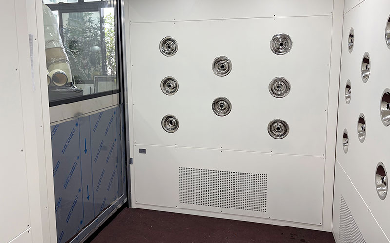
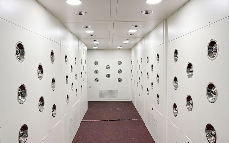
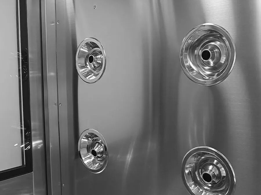
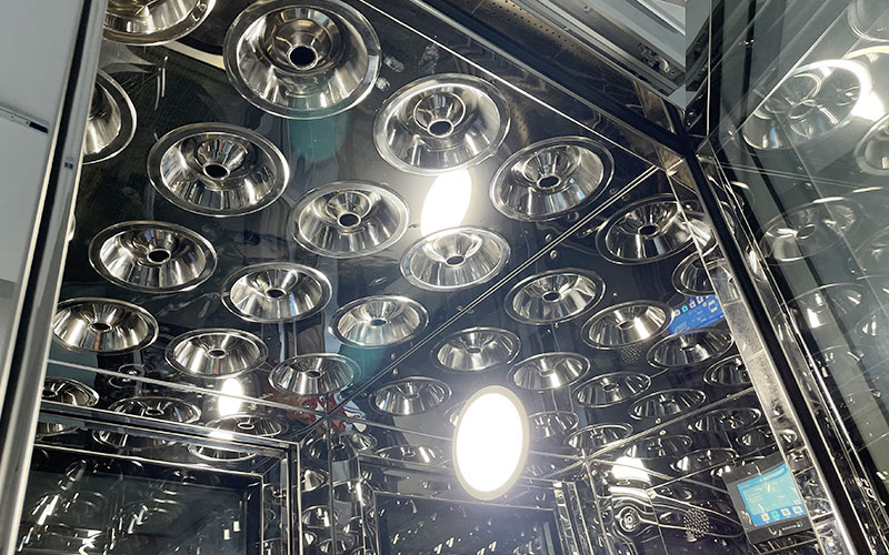
When personnel enter and close the door, the unit automatically activates. Multi-angle nozzles blast high-speed, clean airflow—covering everything from head to toe with 360-degree coverage—to rapidly dislodge contaminants such as dust, hair, and skin flakes adhering to clothing and tools. It does far more than just "blow air"; it acts as an airlock. With an electronic interlocking system, the two doors cannot be opened simultaneously, effectively preventing unpurified air from directly entering the clean zone.


 How robust is the air shower's operating mechanism? 

Upon entry and door closure, the unit automatically triggers. Multi-angle nozzles instantly blast high-speed, clean airflow at velocities exceeding 25 m/s.


 Why is the air shower considered an "essential requirement" for cleanrooms? 

1. Dual-stage filtration system: Air passes through both pre-filters and HEPA filters (H13/H14 grade), achieving a 99.99% filtration efficiency for 0.3-micron particles; the air being blown is itself ultra-clean.


KLC's Air Shower


2. Electronic interlocking "airlock" effect: During the air shower cycle, the front and rear doors are electronically interlocked and cannot be opened. This completely blocks the intrusion of unpurified air, ensuring the clean zone remains uncontaminated.


3. Materials and user-friendly design: Constructed with a corrosion-resistant and easy-to-clean SUS304 stainless steel body, making it the top choice for food and pharmaceutical facilities. Features include smart voice prompts, an LED display, and adjustable air shower duration (10–99 seconds) for hassle-free operation.


KLC's Air Shower


 Maintenance essentials: Extending lifespan and ensuring performance 

Installation is not a "set-it-and-forget-it" affair; regular maintenance is crucial for stable operation:

1. Regular cleaning/replacement of pre-filters: Dust accumulation on the pre-filter mesh reduces airflow velocity; the non-woven filter media should be cleaned promptly. 2. Monitor the status of the HEPA filter: If airflow velocity does not return to normal after cleaning the pre-filter, the HEPA filter is clogged and requires replacement.

3. Check airflow velocity and cleanliness: Conduct regular tests using an anemometer and a particle counter to ensure compliance with standards.

4. Inspect the electronic interlock: Ensure that both doors cannot be opened simultaneously; otherwise, the airlock function will fail.

5. Inspect electrical wiring: Periodically check for circuit faults to prevent issues such as jammed latches.

An air shower is more than just a device that blows air; it serves as the first line of defense for quality. Whether ensuring pharmaceutical safety, chip yields, or food hygiene, this "purification gateway" plays a crucial role. Selecting the right model, using the equipment correctly, and performing regular maintenance are essential to ensuring that every process within the cleanroom stands up to scrutiny.

Top

Air Showers The "Gatekeepers" of Cleanrooms

An air shower is a small chamber equipped with a "high-velocity air blast" function, serving as a mandatory passageway for personnel or goods entering a cleanroom.

Its operating principle is straightforward: a fan draws in ambient air, passing it first through a pre-filter and then through a HEPA filter (with a filtration efficiency exceeding 99.99%) to produce ultra-clean air. This air is then blasted from nozzles at speeds exceeding 20 m/s onto the person inside. This powerful airflow effectively dislodges tiny contaminants—such as dust and skin flakes—adhering to clothing, hair, and carried items. The dislodged particles are captured by the system and recirculated through the filtration loop. Additionally, the dual-door interlocking design (ensuring one door cannot open while the other is open) acts as an airlock, preventing unpurified air from directly entering the cleanroom.


 The Air Shower "Family Tree": Types and Selection 

There is a wide variety of air showers on the market; choosing the wrong one not only wastes money but can also cause long queues at the workshop entrance during peak hours.

First, determine your cleanroom classification requirements: if your workshop is ISO Class 8 (Class 100,000), standard gowning procedures may suffice; however, for ISO Class 7 (Class 10,000) and above, an air shower is "highly recommended" or even mandatory.

Select the model based on "throughput capacity"—this is the most critical factor. Do not rely merely on a subjective sense of "size"; instead, calculate the number of people who need to pass through within a 10-minute peak period. Choosing a unit that is too small causes workers to queue, delaying production, while choosing one that is too large wastes space and budget.


Type

Applicable Scenarios

10-minute throughput capacity (approx.)

Single-person single/double air shower

Small workshop, ≤30 people during peak periods.

30 people

Two-person, dual-air-shower unit

Medium-sized workshop; 30–60 people during peak periods.

60 people

Three-person dual-blow / tunnel-type

Large-scale workshop; accommodates 60 or more people during peak periods or operates with continuous production.

Over 90 people (walk-through type allowing continuous passage)


Material determines lifespan and compliance: Industries requiring frequent cleaning and disinfection—such as food, pharmaceuticals, and cosmetics—must use stainless steel (SUS304 or 316) to ensure corrosion and rust resistance. For general industries like electronics, lower-cost powder-coated cold-rolled steel is a viable option.


KLC's Air Shower


 "Pitfalls" that manufacturers won't explicitly tell you about. 

Industry veterans reveal certain "unspoken rules" regarding air shower selection; overlook them, and you might run into trouble:

Air speed isn't the only factor; uniformity matters more. Don't just listen to sales pitches boasting "25 m/s air speed"; the key is whether the airflow covers the entire body. Poor nozzle layout—where air hits only the chest while missing the underarms and trouser legs—renders the process ineffective. A good design creates cross-covering "turbulent flow," leaving no dead zones.

The interlocking mechanism is a "lifesaver": Door interlocking is crucial for preventing contamination of the cleanroom. Low-end models use electromagnetic locks that fail during power outages; pneumatic cylinder interlocks offer higher reliability by maintaining the lock mechanically—a preferred choice for food and pharmaceutical plants.

Don't overlook a key metric: noise. If the air shower exceeds 75 decibels, operators may find the noise unbearable and try to "skip" the air shower process, rendering your cleanroom management protocols useless. During acceptance testing, it is essential to ensure the noise level is ≤65 dB at a distance of one meter.


KLC's Air Shower


 Making the most of it: Proper use and maintenance. 

Purchasing the unit is just the first step; proper usage is what really counts.

Operational workflow: Enter the air shower and close the door; the air shower cycle starts automatically (or via infrared sensor), locking both doors. Once the cycle ends (usually 15–20 seconds), the entrance door remains locked, allowing exit only through the exit door. Forcing both doors open simultaneously is strictly prohibited, as it can damage the interlocking system.

Daily maintenance is the key to longevity: The most common failure point isn't the fan, but filter clogging.

Pre-filter: Acts like a "face mask"; requires cleaning or replacement every 1–6 months. If you notice reduced airflow, check this filter first for darkening or dust accumulation.

HEPA filter: Acts like the "lungs"; typically requires replacement every 6–12 months. After the replacement, you must use a particle counter to inspect the frame and ensure there are no leaks; otherwise, it will turn into a "dust-blowing chamber."

Top

An Analysis of Laminar Flow Hood Applications Across Industries From Core Principles to Practical Scenarios

In industrial production and scientific research, many critical processes are extremely sensitive to airborne dust and microorganisms; a single speck of dust can ruin a microchip, and one bacterium can render an entire batch of pharmaceuticals unfit for use. Laminar flow hoods are air purification units designed specifically to meet these localized "Class 100" cleanliness requirements.


 What is a laminar flow hood? How does it work? 

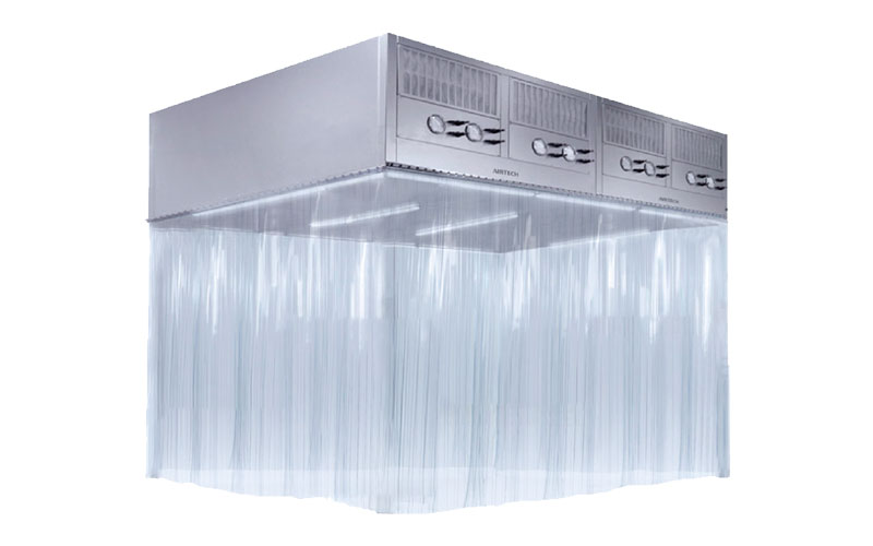
A laminar flow hood is an air purification device that provides a localized, high-cleanliness environment. It can be flexibly installed above specific process points requiring high cleanliness—either as a standalone unit or combined with others to form a continuous clean zone. Its core operating principle is straightforward: a fan draws in air, which passes through two stages of filtration (pre-filters and HEPA/ULPA filters). The air is then guided through a flow-equalizing device to create a uniform, stable, vertical unidirectional airflow (i.e., "laminar flow") that continuously sweeps over the work area.


Laminar Flow Hood vs. FFU: What is the difference? These two concepts are often confused within the industry. An FFU (Fan Filter Unit) is a modular device that integrates a fan and a high-efficiency filter; it emphasizes "plug-and-play" flexibility and is designed for large-scale installation within cleanroom ceiling grids. In contrast, a laminar flow hood features a more complete structure—typically including its own housing and flow-equalization layer—making it better suited for creating a localized Class 100 environment at specific points within lower-grade cleanrooms. Simply put: FFUs are like "building materials," while laminar flow hoods are like "equipment."


KLC's Laminar Flow Hood


 Key Application Areas 


Electronics Manufacturing: Guarding Against Dust

Processes such as chip packaging, LCD panel assembly, and precision optical instrument manufacturing demand extremely strict control over dust particles ≥0.5μm in size. Laminar flow hoods provide a localized clean environment of ISO Class 5 (Class 100) or higher. In the electronics industry, they are often used in conjunction with clean booths or arranged in series along production lines to form "clean laminar flow zones," ensuring that critical workstations remain free from contamination.


Food Processing: Ensuring Biosafety

Processes such as probiotic cultivation, aseptic packaging, and dairy product filling also rely on the localized clean environments provided by laminar flow hoods. Unlike the pharmaceutical industry, which prioritizes sterility, the food industry focuses more on controlling microbial contamination and extending product shelf life. Laminar flow hoods effectively isolate products from potential contamination caused by operators and the surrounding environment by continuously delivering clean air.


Healthcare and Scientific Research: Ensuring Operational Safety

In hospital settings, laminar flow hoods are used for procedures requiring sterile conditions, such as bone marrow transplant wards, chemotherapy drug preparation, and the compounding of intravenous nutritional solutions. In laboratories, they provide a stable and reliable localized Class 100 environment for tasks like cell culture and microbial inoculation.


Installation Methods and Selection Guide

Laminar flow hoods come in three main configurations: suspended (ceiling-mounted, suitable for fixed workstations), floor-stand mounted (suitable for locations where ceiling suspension is not feasible), and mobile (laminar flow carts; these offer flexible relocation and include models with UPS battery backup providing 2–8 hours of runtime).


 Key Performance Indicators (Based on a standard Class 100 laminar flow hood): 

Cleanliness: Dust particles ≥0.5 μm in the work area ≤3.5 particles/liter (FS209E Class 100)

Average Airflow Velocity: 0.25–0.55 m/s (adjustable)

Noise Level: ≤64 dB(A)

Power Supply: 220V, 50Hz


 Maintenance Essentials and Common Misconceptions 

1. Regular HEPA Filter Replacement: It is recommended to replace pre-filters every 1–6 months and HEPA filters every 6–12 months. These filters cannot be washed; a leak test is recommended after replacement to verify the seal.

2. Power Off During Malfunctions: If the equipment operates abnormally, cut off the power immediately and contact a professional for service; do not attempt to disassemble the unit yourself.

3. Environmental Limitations: Operating temperature must not exceed 50°C, and the use of open flames indoors is strictly prohibited.

Top

Five Common Leak Detection Methods for HEPA Filters

Leak detection for HEPA filters is a standard testing requirement for cleanrooms and a mandatory procedure for pharmaceutical companies; an increasing number of facilities in sectors such as healthcare, electronics, food processing, and cosmetics are also adopting these testing protocols.

The following section details the specific methods used for HEPA filter leak detection.


 I. Sodium Flame Method 

The test aerosol source for the sodium flame method is a poly disperse sodium chloride salt mist; the measured parameter is the brightness of a hydrogen flame when exposed to the salt-laden mist.

Saltwater is atomized by compressed air and dried to form tiny salt crystal particles, which enter the airflow duct; air samples are collected both upstream and downstream of the air filter.

The salt-laden air causes the hydrogen flame to turn blue and increase in brightness. Flame brightness is used to gauge the salt mist concentration, thereby determining the filter's filtration efficiency.

The primary testing instrument is a flame photometer. This method has relatively low sensitivity and is unsuitable for testing HEPA filters.


 II. Oil Mist Method 

The test aerosol source for the oil mist method is oil mist; the measured parameter is the turbidity of the air containing the mist. Filtration efficiency is determined by comparing the turbidity of air samples taken upstream and downstream of the air filter.

German standards specify the use of paraffin oil, with oil mist particle sizes ranging from 0.3 to 0.5 micrometers. This method carries a risk of damaging the filter during testing, does not provide direct readings, and is time-consuming.


 III. DOP Method 

This method was once the internationally standard approach for testing HEPA filters.


HEPA filters DOP Test Method


The test aerosol source consists of monodisperse dioctyl phthalate (DOP) droplets with a diameter of 0.3 micrometers—also known as "Hot DOP"—and the measured parameter is the turbidity of the DOP-laden air.

DOP liquid is heated into vapor, which condenses into tiny droplets under specific conditions. After filtering out droplets that are too large or too small, particles of approximately 0.3 micrometers remain and enter the airflow duct. Filtration efficiency for 0.3-micrometer particles is determined by measuring the turbidity of air samples upstream and downstream of the air filter.


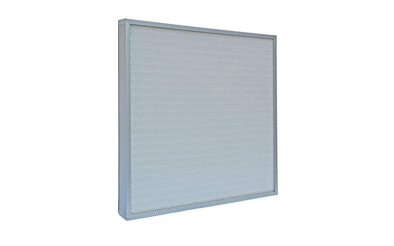
Mini-pleat Panel Filter


 IV. Fluorescence Method 

The test aerosol source for the fluorescence method is sodium fluorescein dust generated by a sprayer. The testing procedure involves first taking samples upstream and downstream of the filter sponge, then dissolving the sodium fluorescein from the sampling filter paper into water. Next, the fluorescence intensity of the resulting solution is measured under specific conditions; since this intensity correlates with the mass of the captured dust, the filter's efficiency can be calculated.


 V. Particle Counting Method 

This method is widely used in Europe, and the testing procedure for ultra-low penetration air (ULPA) filters in the United States is similar; it is currently the mainstream international method for testing sponge filters.

The dust source consists of polydisperse liquid droplets or solid dust particles of a specific size. In some cases, filter manufacturers may use atmospheric dust or other specific types of dust to meet a user's special requirements.

If a condensation nucleus counter is used for the test, a monodisperse test dust source with a known particle size is required. The primary measuring instruments are high-flow-rate laser particle counters or condensation nucleus counters.

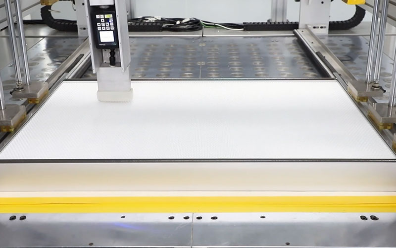
A counter is used to scan the entire downstream face of the filter; it records the number of dust particles at each point, allowing for a comparison of local efficiencies across different locations.

Top

KLC's 450°C High-Temperature Separator Filter Solving High-Temperature Filtration Challenges in Spray Painting and Automotive Manufacturing

Selecting medium-efficiency aluminum separator filters for high-temperature production environments—such as spray painting facilities and automotive plants—has long been a headache for engineers. Conventional products typically have a temperature limit of 250°C to 300°C; once operating temperatures exceed this threshold, the fiberglass filter media suffers irreversible damage, such as fiber breakage, shedding, melting, or even carbonization and blackening. This not only causes a sharp decline in filtration efficiency but also leads to frequent equipment downtime and the need for consumable replacements, imposing a heavy cost burden and causing schedule delays for continuous production lines.


To address this persistent industry pain point, KLC has launched a aluminum separator filter capable of withstanding temperatures up to 450°C. By raising the temperature limit to 450°C, the product fundamentally resolves the issue of filter media failure in high-temperature conditions.


 Three core technologies deliver exceptional heat resistance: 


Specialized Filter Media: The fiberglass structure has been optimized for extreme 450°C temperatures. By carefully selecting high-temperature resistant specialty fibers and high-performance binders—and utilizing a wet-laid manufacturing process—we ensure the filter paper maintains structural stability without shrinking or becoming brittle under high heat.


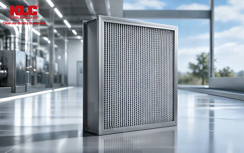
KLC’s High-Temperature Separator Filter


Reinforced Frame: The outer frame undergoes an anti-corrosion aluminizing treatment, significantly enhancing overall structural rigidity and oxidation resistance, ensuring excellent dimensional stability even under continuous thermal shock.


Performance Assurance: The filter maintains stable dust-holding capacity and low resistance at the medium-efficiency level. It is perfectly suited to the air purification needs of spray painting lines and automotive manufacturing workshops, safeguarding the quality of the final product.


KLC’s High-Temperature Separator Filter


Furthermore, KLC possesses exclusive testing equipment for measuring dust-holding capacity across all filter grades (pre-, medium-, and high-efficiency). Each product comes with a professional performance test report, and all data regarding filtration efficiency and service life are fully documented and verifiable, ensuring well-founded product selection and greater peace of mind during use.

Top

The Invisible Cornerstone Cleanroom Technology, Industry, and Future Trends

Beyond the macroscopic world we take for granted lies a microscopic realm that demands near-absolute purity. In this domain, a speck of dust far finer than a human hair is enough to ruin a product of immense value. The guardian of this realm is the cleanroom—a space where the concentration of airborne particles is strictly controlled. These facilities are designed and operated to minimize the introduction, generation, and retention of particles indoors, while precisely regulating parameters such as temperature, humidity, and pressure.


 Definitions and Standards: More Than Just "Clean" 

A cleanroom is far more than merely a "spotless room"; it is governed by a rigorous set of technical standards and operational definitions.

As-built: The facility is fully constructed and all utility systems are operational, but no production equipment, materials, or personnel are present.

In-operation: The facility is running under specified conditions, with designated personnel present and actively working.

These definitions serve as the cornerstone for cleanroom design, testing, and acceptance, ensuring that cleanliness assessments remain comparable across different stages.


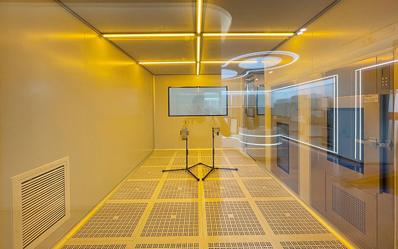
KLC'S Cleanroom


At the heart of a cleanroom lies complex system integration. A complete cleanroom typically comprises five major systems: the enclosure system (walls, ceilings, and floors), the HVAC system (supplying clean air and controlling temperature and humidity), the electrical system, the plumbing and drainage system, and the automatic control system. Airflow patterns are critical to the design, generally categorized into unidirectional flow (air moves at a uniform speed in a single direction, offering extremely high cleanliness) and non-unidirectional flow (air mixes to dilute particles, suitable for environments with slightly lower cleanliness requirements).


Cleanrooms serve as "invisible infrastructure" for numerous high-tech and consumer-facing industries, supporting a wide range of downstream applications and diverse needs.


Semiconductors and Electronic Information: This is the primary and most demanding application sector for high-end cleanrooms. As chip manufacturing processes advance to the nanometer scale, even the tiniest airborne particles can cause circuit short-circuits or a drastic drop in production yields. Cleanroom engineering typically accounts for 5–10% of the total capital expenditure in integrated circuit manufacturing. The boom in AI and high-performance computing is driving a new cycle of capacity expansion among global wafer fabs, directly fueling demand for high-grade cleanrooms.


Other sectors—such as advanced displays (e.g., OLED panels), new energy (e.g., photovoltaics and lithium batteries), and food and pharmaceutical manufacturing—also represent significant application areas for cleanrooms.


 Industry Trends: AI-Driven Growth and Global Expansion 

The cleanroom industry is currently in an upward cycle driven by both technological revolutions and the restructuring of global supply chains.


Technological Upgrades and Model Transformation: To address global competition and cost pressures, the industry is evolving toward greater intelligence, sustainability, and modularity. Modular cleanrooms are regarded as a key capability; by leveraging domestic supply chain and production strengths to prefabricate components in factories, companies can effectively reduce on-site labor costs and timeline uncertainties for overseas projects, thereby establishing a differentiated competitive advantage.


In summary, cleanrooms have evolved from mere "auxiliary facilities" into core infrastructure underpinning modern high-tech manufacturing. Amidst the waves of global technological competition and industrial transformation, their strategic value and market potential are becoming increasingly prominent.

Top

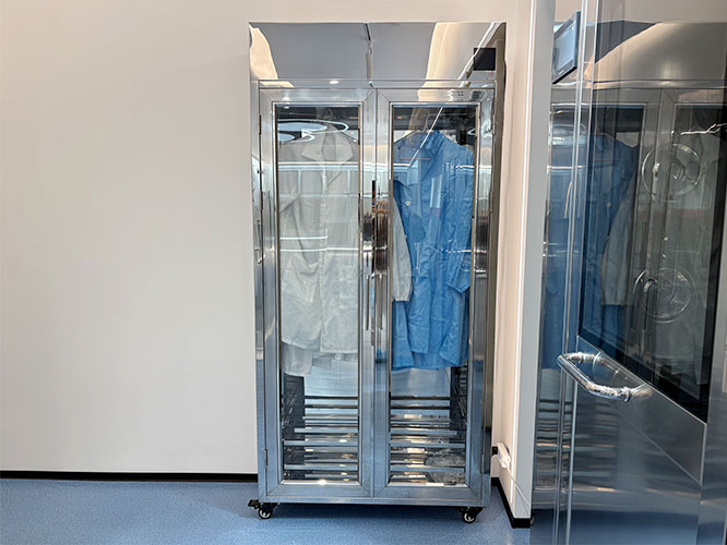
Why Are Dust-Free Wardrobes Essential for Cleanroom Workshops?

Cleanroom workshops in food processing plants demand extremely high levels of environmental cleanliness. Contaminants such as dust, bacteria, and hair carried on employees' clothing can easily contaminate raw materials and finished products if they enter the workshop without proper treatment. While standard wardrobes merely provide storage, dust-free wardrobes—equipped with powerful disinfection and storage capabilities—have become indispensable equipment for cleanrooms. They not only ensure the cleanliness and hygiene of employee attire but also mitigate the risk of human-induced food contamination, safeguarding food safety at the source.


 1. High-Efficiency Disinfection and Bacterial Elimination 

Dust-free wardrobes employ various advanced disinfection technologies, such as ultraviolet (UV) light, ozone, and high-temperature sterilization. UV light disrupts the DNA structure of bacteria and viruses, rendering them unable to reproduce; ozone, with its strong oxidizing properties, rapidly breaks down bacterial cell walls and proteins; and high-temperature sterilization uses hot steam to effectively kill various microorganisms on the clothing. The synergistic effect of these multiple disinfection methods ensures comprehensive, thorough sanitization, leaving no hiding place for harmful microorganisms.


KLC' s Dust-Free Wardrobes


 2. Constant Temperature and Dehumidification for Dryness 

Damp environments foster the growth of mold and bacteria, but dust-free wardrobes feature constant-temperature dehumidification capabilities. By maintaining internal temperature and humidity within optimal ranges, they ensure that clothing remains consistently dry. Whether during the humid rainy season or in environments with significant temperature fluctuations, employees can wear dry, clean work uniforms; this enhances comfort while further protecting the workshop's clean environment.


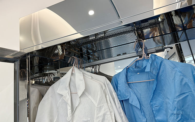
KLC' s Dust-Free Wardrobes


 3. Logical Zoning and Categorized Storage 

Dust-free wardrobes feature a well-designed interior with distinct functional zones for the organized storage of items such as work uniforms, masks, hats, and gloves. This layout not only prevents cross-contamination between different items but also allows employees to quickly locate what they need, thereby saving time and boosting work efficiency. Additionally, the wardrobe's capacity can be customized based on the number of workshop employees, meeting the specific needs of enterprises of various sizes.

Top